Replace a Dreamcast’s fuse
While consoles that accept standard C7 plugs are convenient, no need to keep track of unique power bricks, there is always the danger in 230V countries of plugging a 110V console directly into the mains. Unfortunately this happened to my Japanese Dreamcast. Fortunately the only damage was a blown fuse in the power supply, which can be replaced.
The only complexity is that unlike consoles such as the 3DO, the Dreamcast doesn’t use a standard fuse (a glass capsule containing the fuse wire) but instead uses a sealed unit which is directly soldered to the power supply board. However using parts easily sourced from eBay. It’s possible to both replace the fuse and make it much easier to replace in the future should further voltage related incidents occur.
In place of the original fuse, I used an inline 5x20mm fuse holder (picture) and a 2A 250V fast blow 5x20mm fuse (picture). Both of which were bought for next to nothing from eBay sellers.
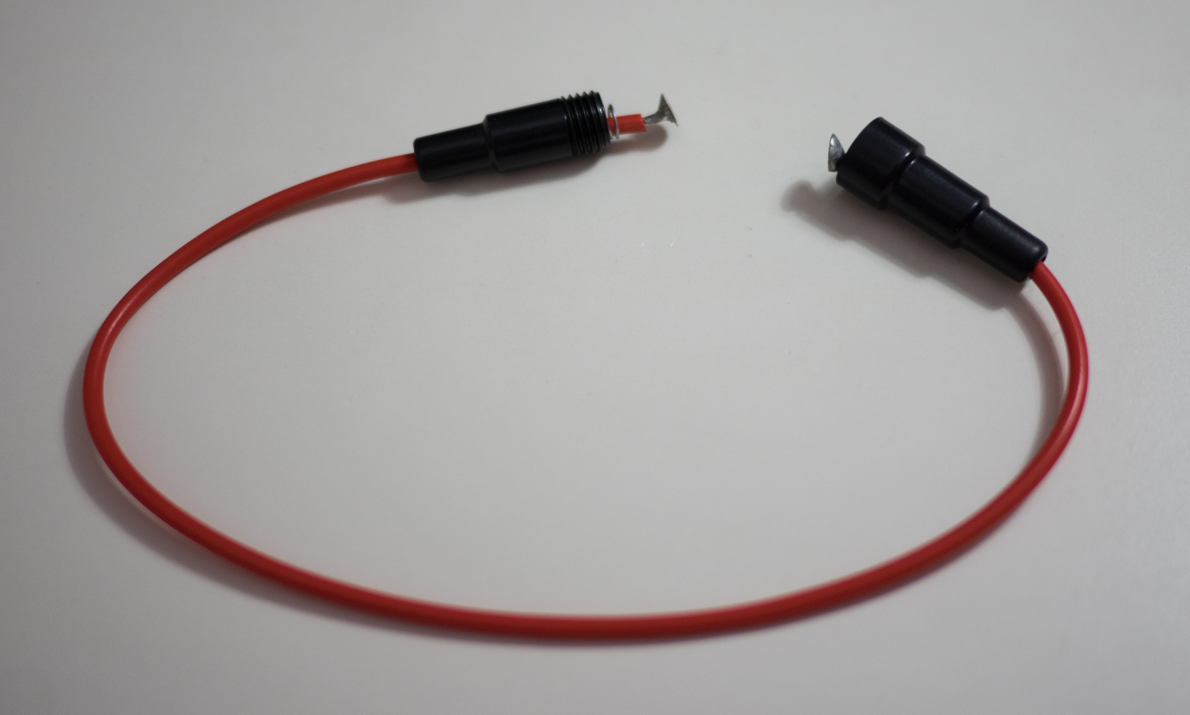
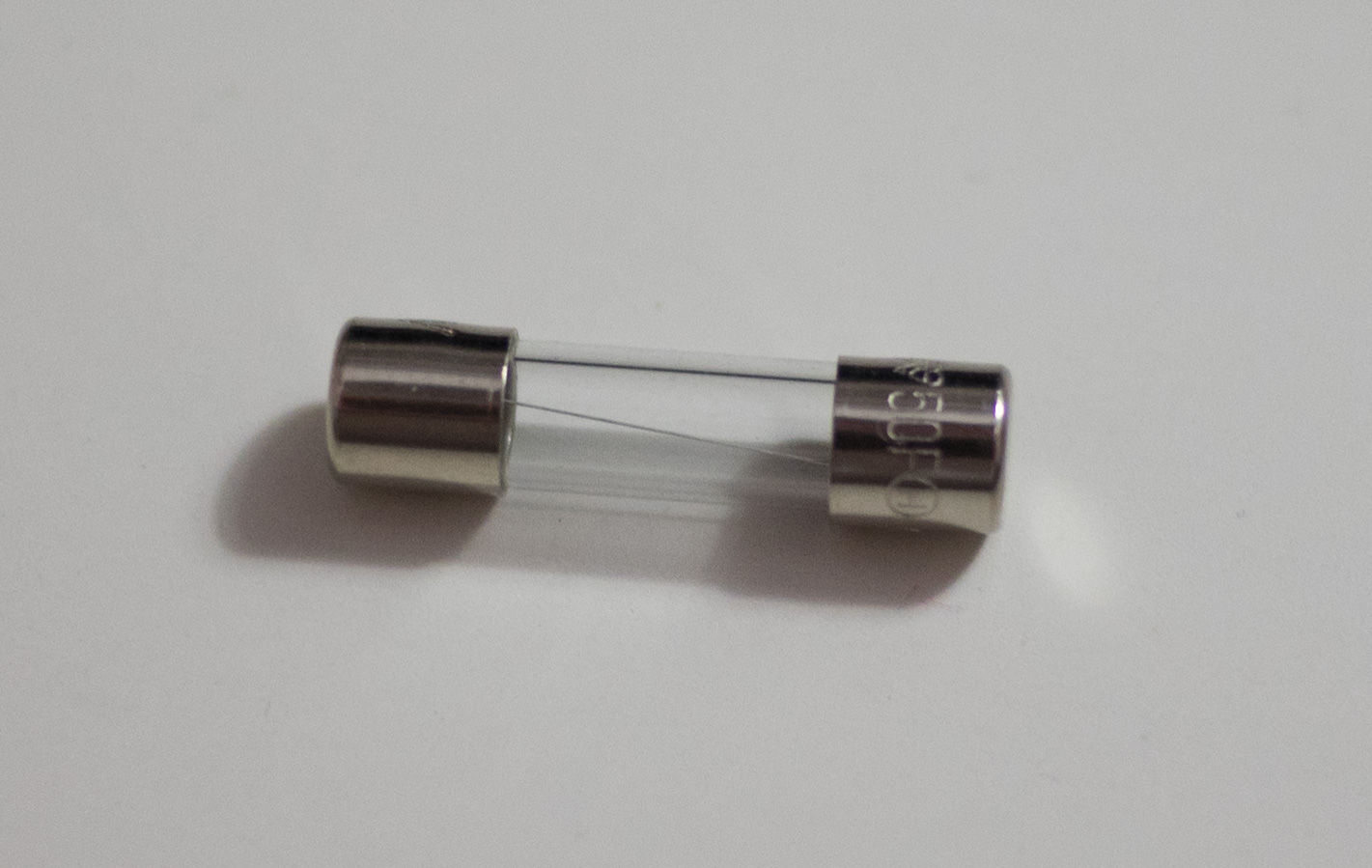
Along with these parts I used:
- A cross head (Phillips) screwdriver.
- A soldering iron (and some solder).
- A solder sucker (a desoldering iron or desoldering braid would also work).
1: Remove the power supply board from the case⌗
Opening the Dreamcast is so simple I won’t go into details, just remove the four screws on the base (one of which is behind the modem cover). The power supply board is the module next to the drive assembly.
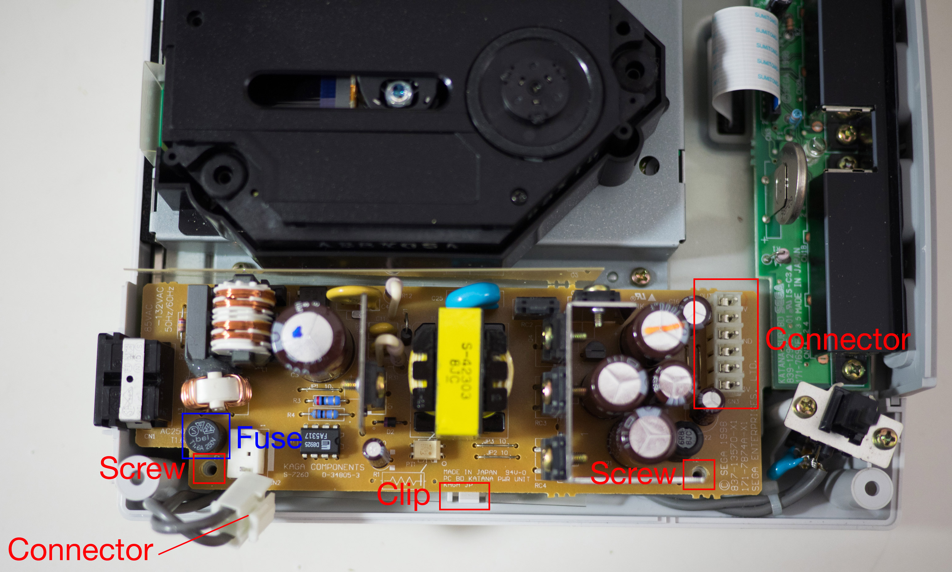
The image below shows the layout of the board and what’s holding it in place. Remove the two screws and the two cord cable. Then (gently) push back the clip and pull the board directly upwards. The six pin connector only uses friction to maintain contact and once clear of the clip, the board should slide out.
2: Desolder the old fuse⌗
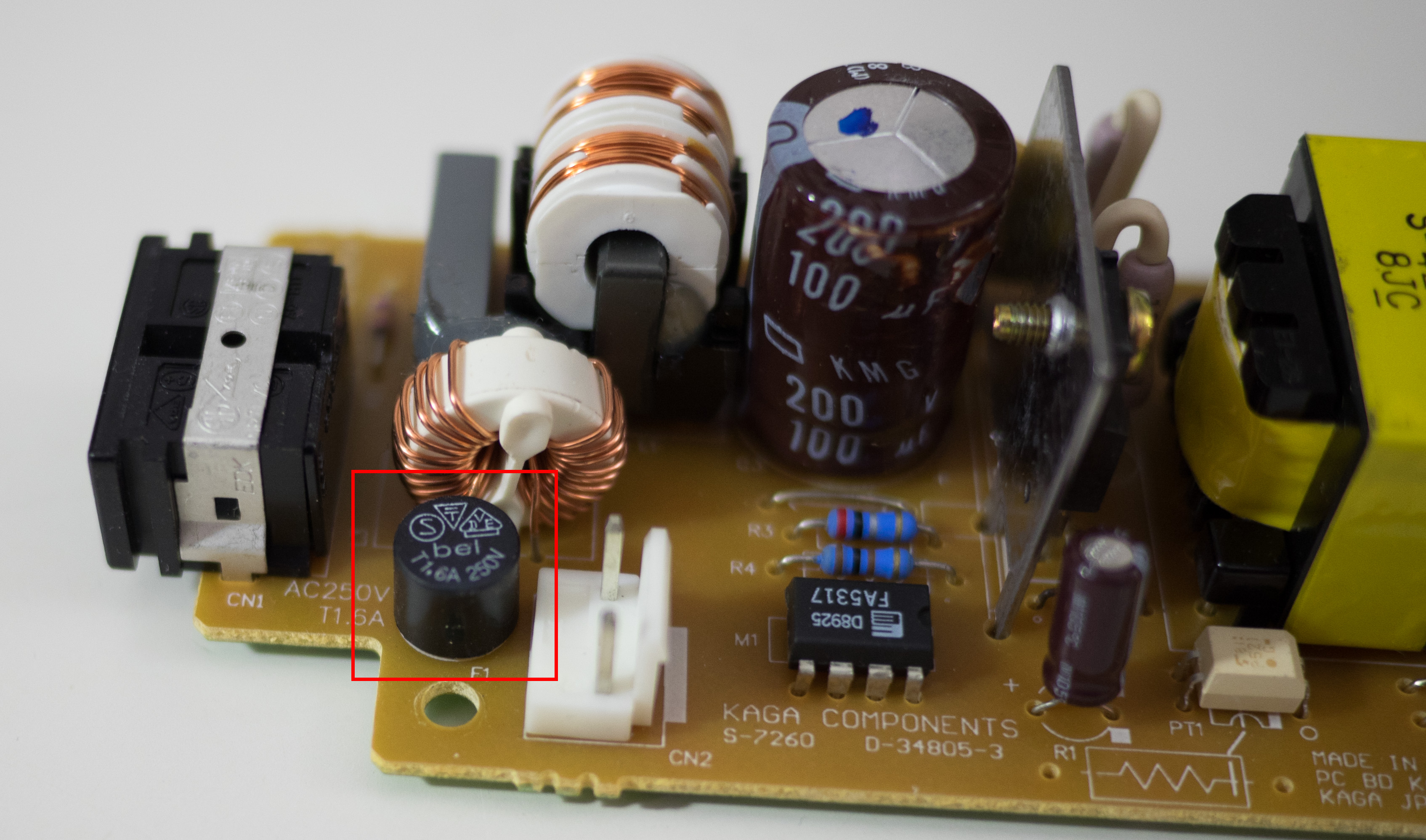
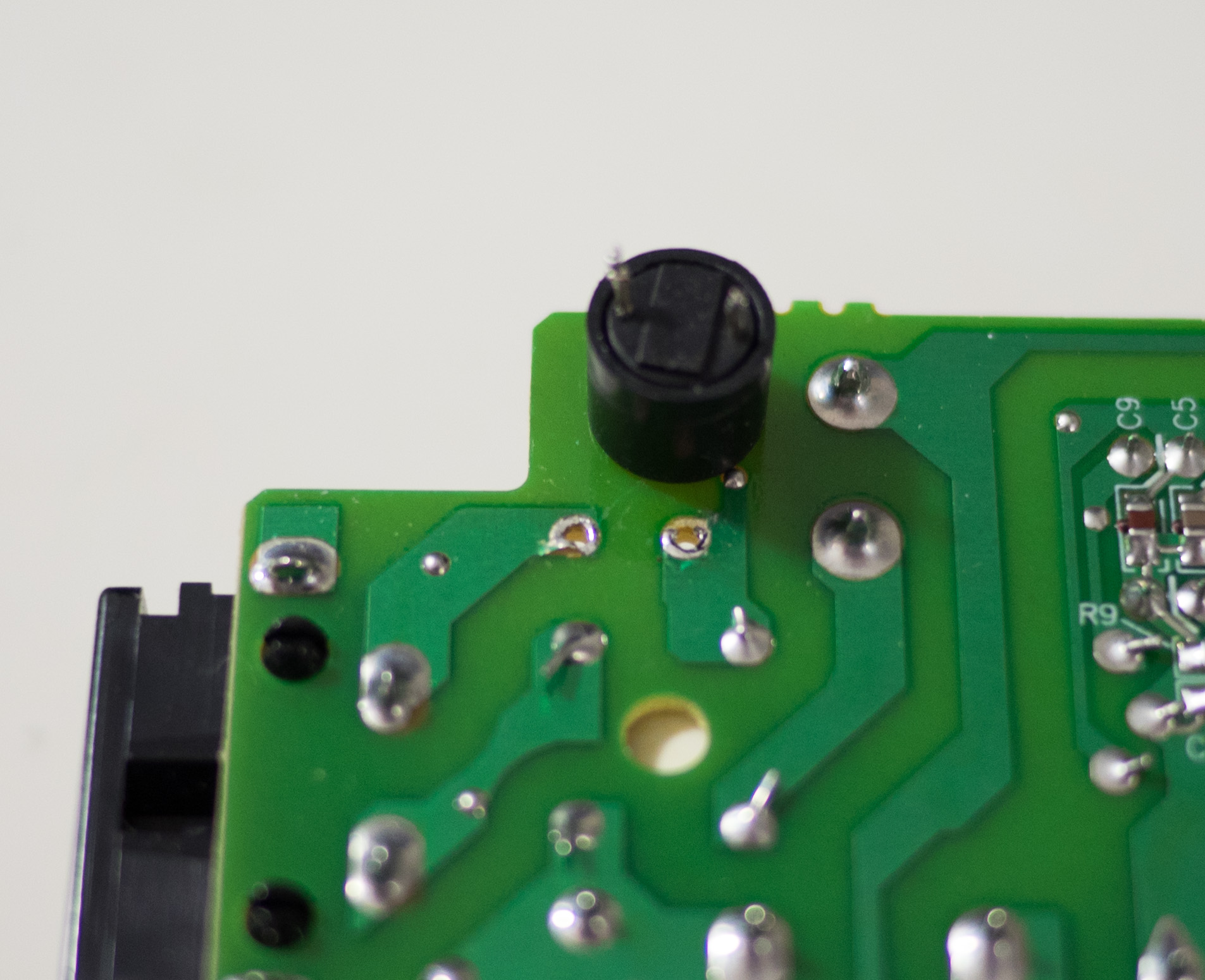
The image below shows the position of fuse on the top of the power supply board.
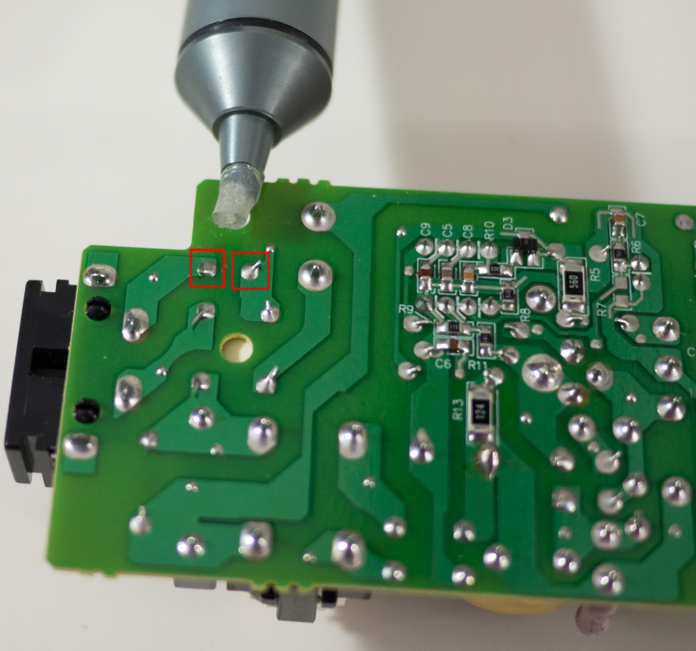
The next image shows the same view from the underside of the board. The two highlighted pads are the ones that must be desoldered, either using braid or a solder sucker/desoldering iron. It’s worth spending time doing this step cleanly to avoid damaging the PCB, or leaving old solder in the holes (which will make it difficult to thread through the leads for the replacement fuse holder).
What you should be left with is a liberated former-fuse and two neat holes on the PCB. Ideally neater holes than I was left with, as I slightly lifted the trace by the left-hand hole. Thankfully it was only minor and didn’t cause any problems when attaching the new fuse.
3: Solder in the new fuse holder⌗
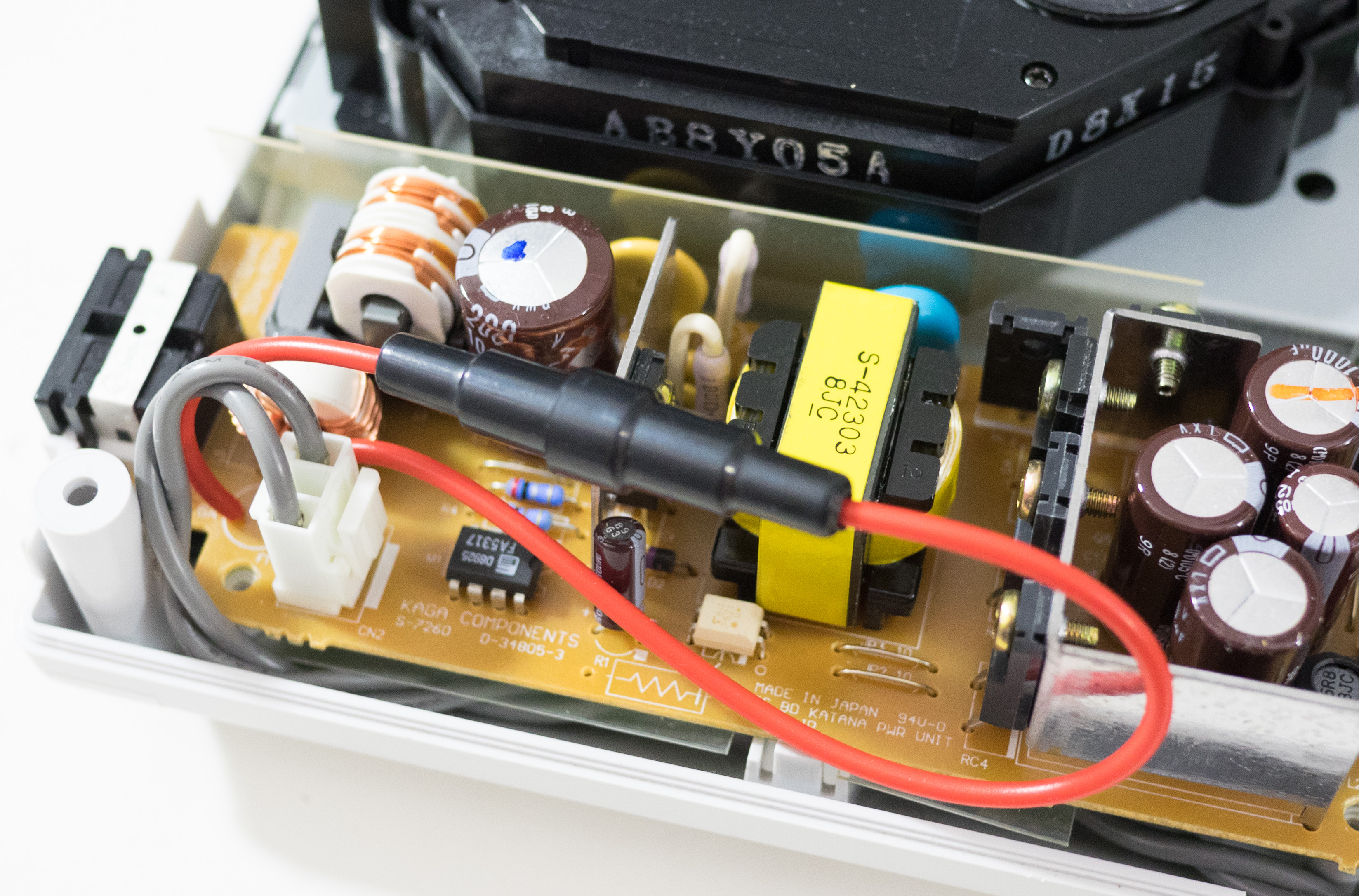
The only potentially tricky part here is making sure to leave enough length in the new fuse holder’s leads to allow it to fold down next to the rest of the components on the power supply board. The picture below shows how I arranged it and in that position, there’s no problems closing the Dreamcast’s case.
The actual attachment of the new holder is through the two holes left by removing the old fuse. Once soldered in place the new fuse can be added to the holder.
4: Reassemble the Dreamcast⌗
This just the reverse of step 1. Align the power supply board with the six pin connector and slide it down until the clip engages. Then plug in the two cord cable and fasten the two screws.
Assuming the new fuse holder has been placed alongside the taller components on the power supply board, the top of the case should pop on and the four screws can be put back in. The Dreamcast should now be back up and running, until you next over-voltage it.