ZX Spectrum Composite output mod
From the Spectrum 128K+ onwards all Spectrums were capable of generating RGB output via the “monitor” socket. This makes connecting them to modern televisions extremely easy. Unfortunately the earlier models only possessed a RF output. This produces the worst possible output and increasingly few displays can demodulate analogue television signals. Luckily the design of the Spectrum makes it very easy to convert the RF output in to a simple composite out.
The Spectrum 16K, 48K and 48K+ generate a composite signal that is then modulated in to a PAL television signal on channel 36. This signal is video only as all audio is output via the internal speaker. Thus getting composite output from the Spectrum just requires the modulator to be removed and composite signal connected to the (formerly RF) socket.
The modification requires the following:
- A cross head (Phillips) screwdriver.
- A soldering iron (and some solder).
- A 100uF 10V capacitor (to decouple the composite output and improve the picture quality).
- A solder sucker or desoldering iron (technically neither of these is required but having one or the other will make things much easier).
- A small, flat bladed screwdriver or needle nose pliers (for opening the modulator box).
1: Disassemble the Spectrum⌗
Remove the screws from the outside of the case and carefully lift the keyboard. Very carefully unplug the keyboard ribbon connectors, making sure not to bend or tear them. Then unscrew the main board from the bottom of the case and remove it.
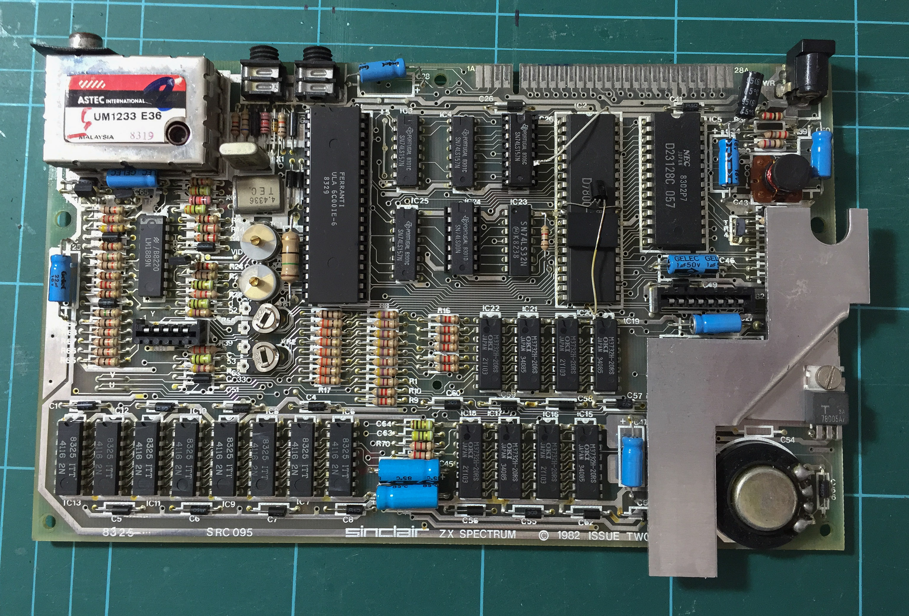
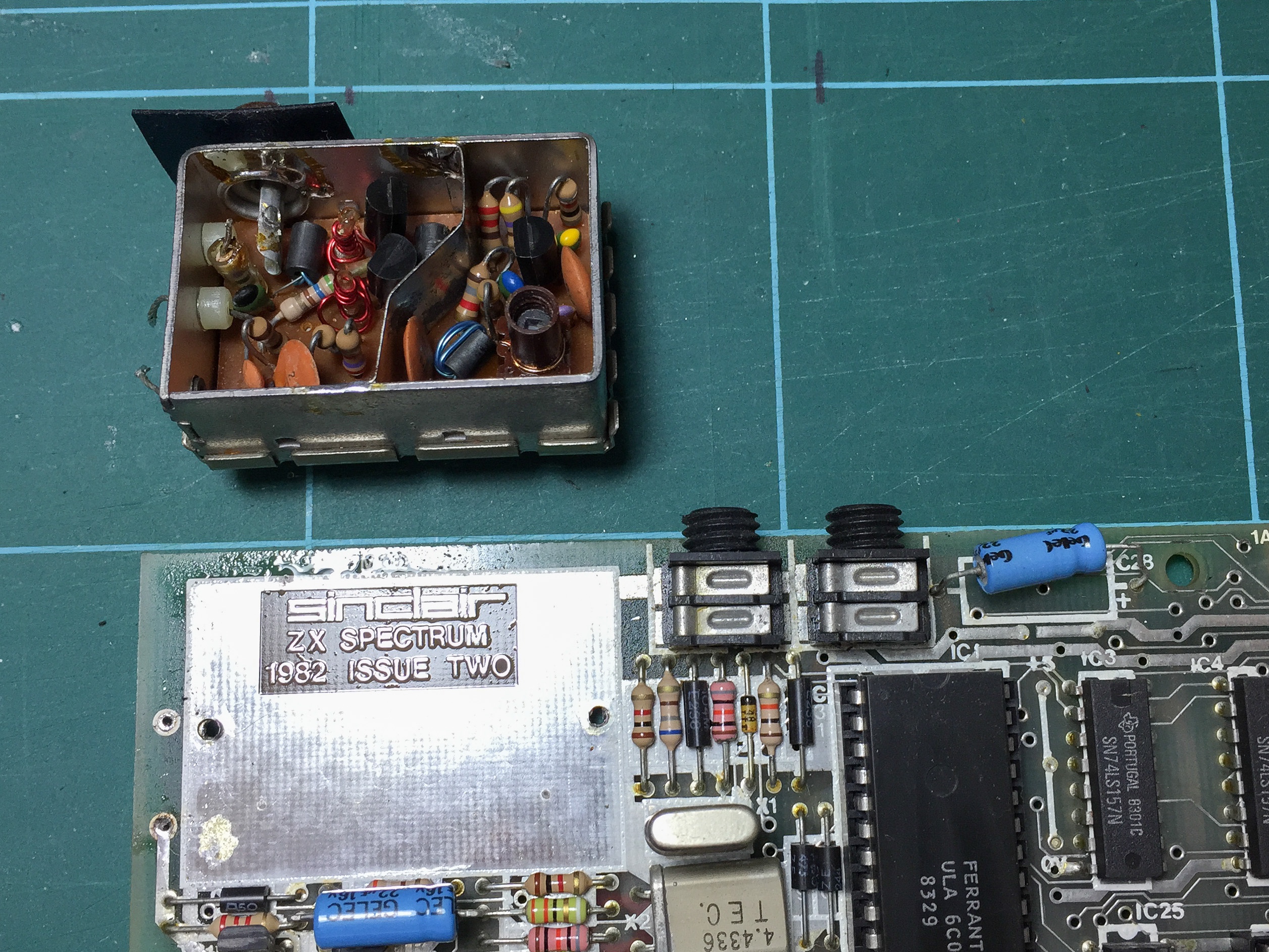
The image below is from a second issue Spectrum 48K; but the basic layout is the same for all pre-128K models.
2: Remove the modulator box lid⌗
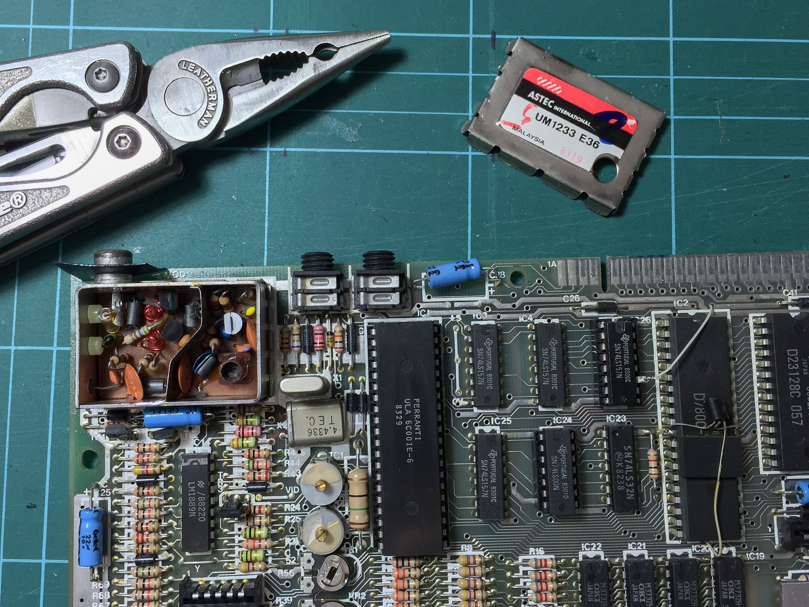
The lid of the modulator box (on the top-left of the main board) is held on by crimped edges. Carefully prise these off using a flat bladed screwdriver or needle nose pliers.
Take care not to damage the main board or any of its components while doing this.
3: Desolder the modulator input wires⌗
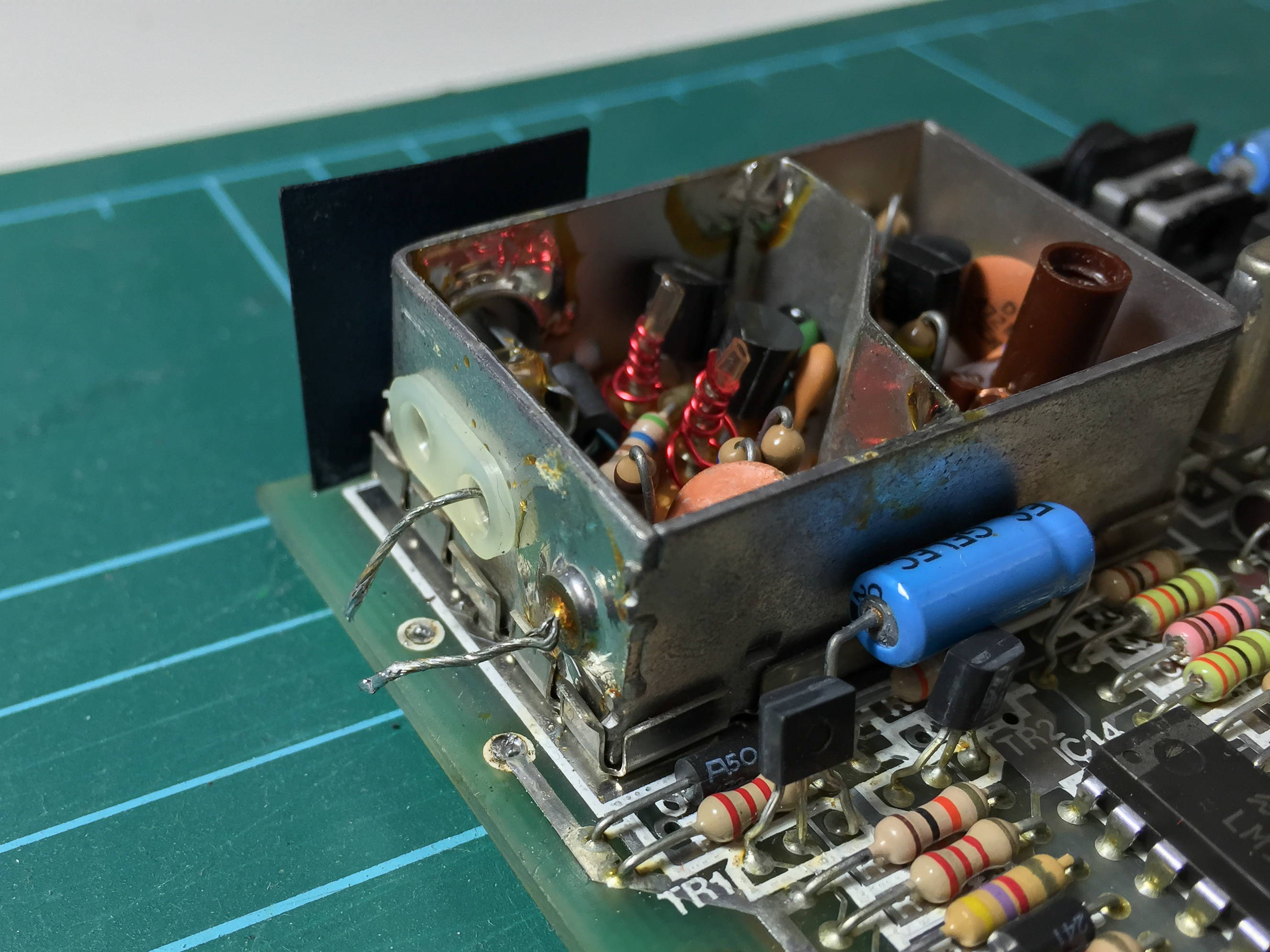
Desolder the two wires leading from the main board in to the modulator box (see image below). These are the composite input and the +5V line that powers the modulator.
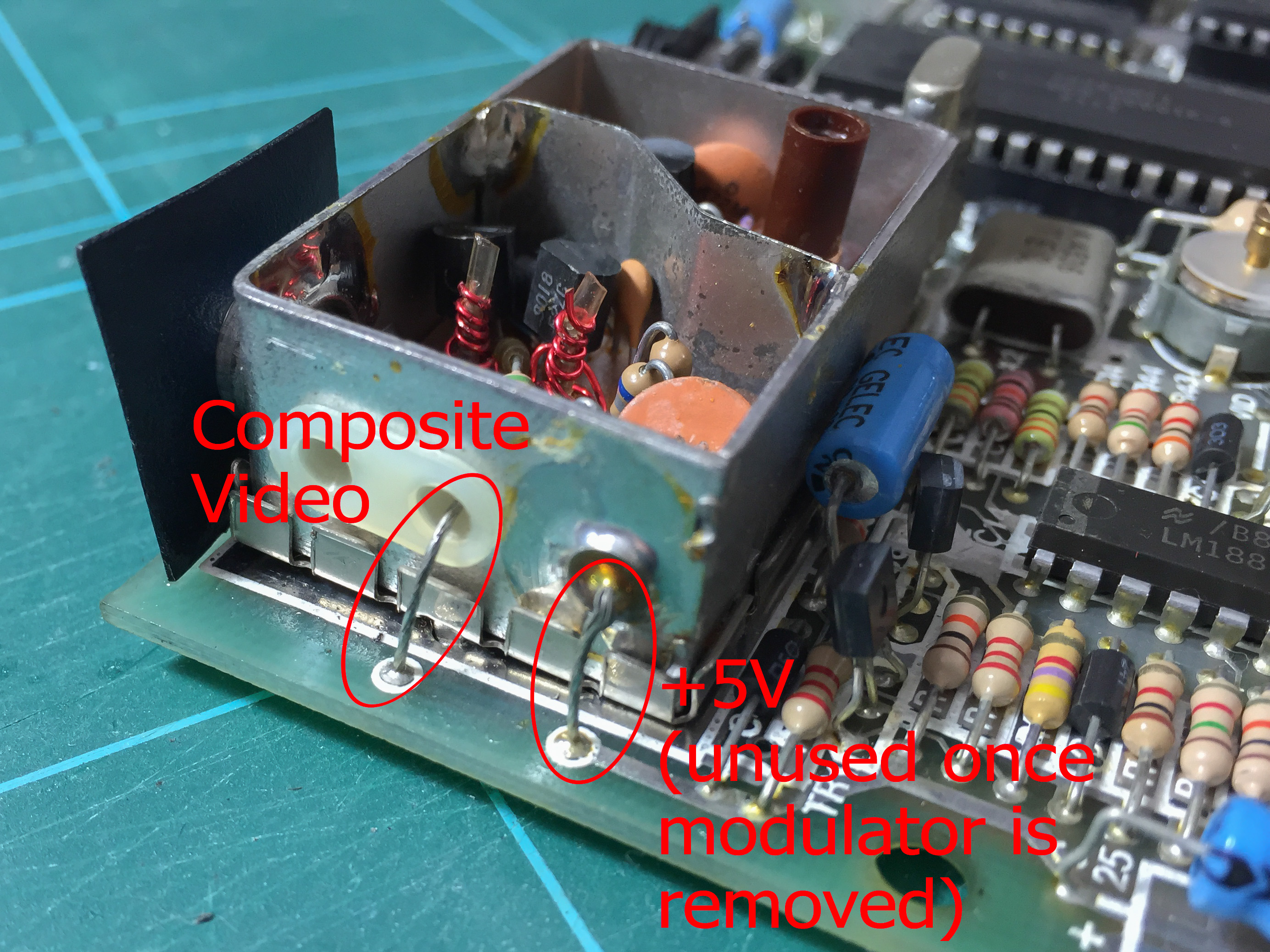
The image below shows the desoldered wires.
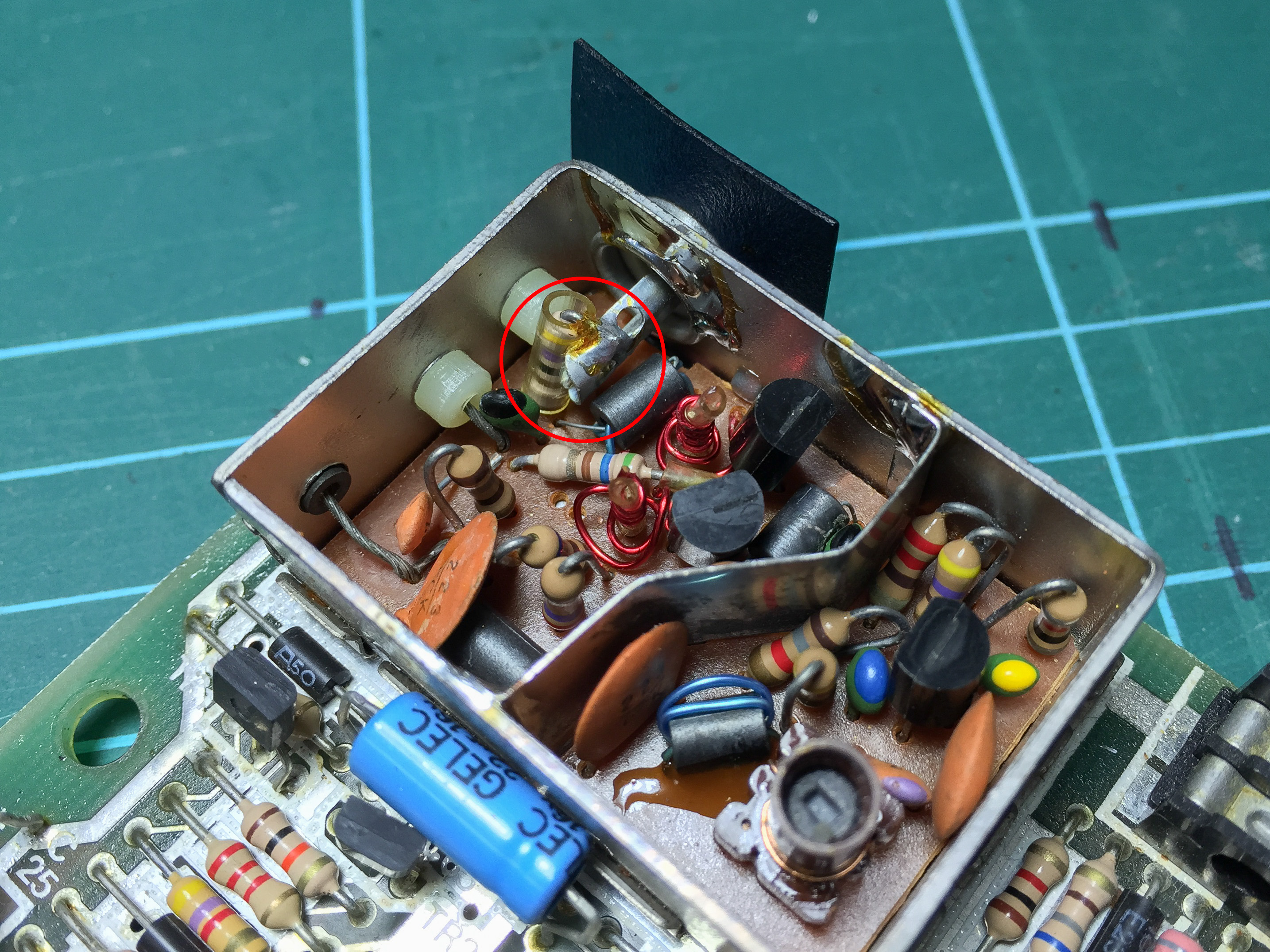
4: Desolder the output resistor⌗
The image below shows the resistor that connects the modulator output to the centre pole of the RF socket. This should be desoldered and eased away from the pole.
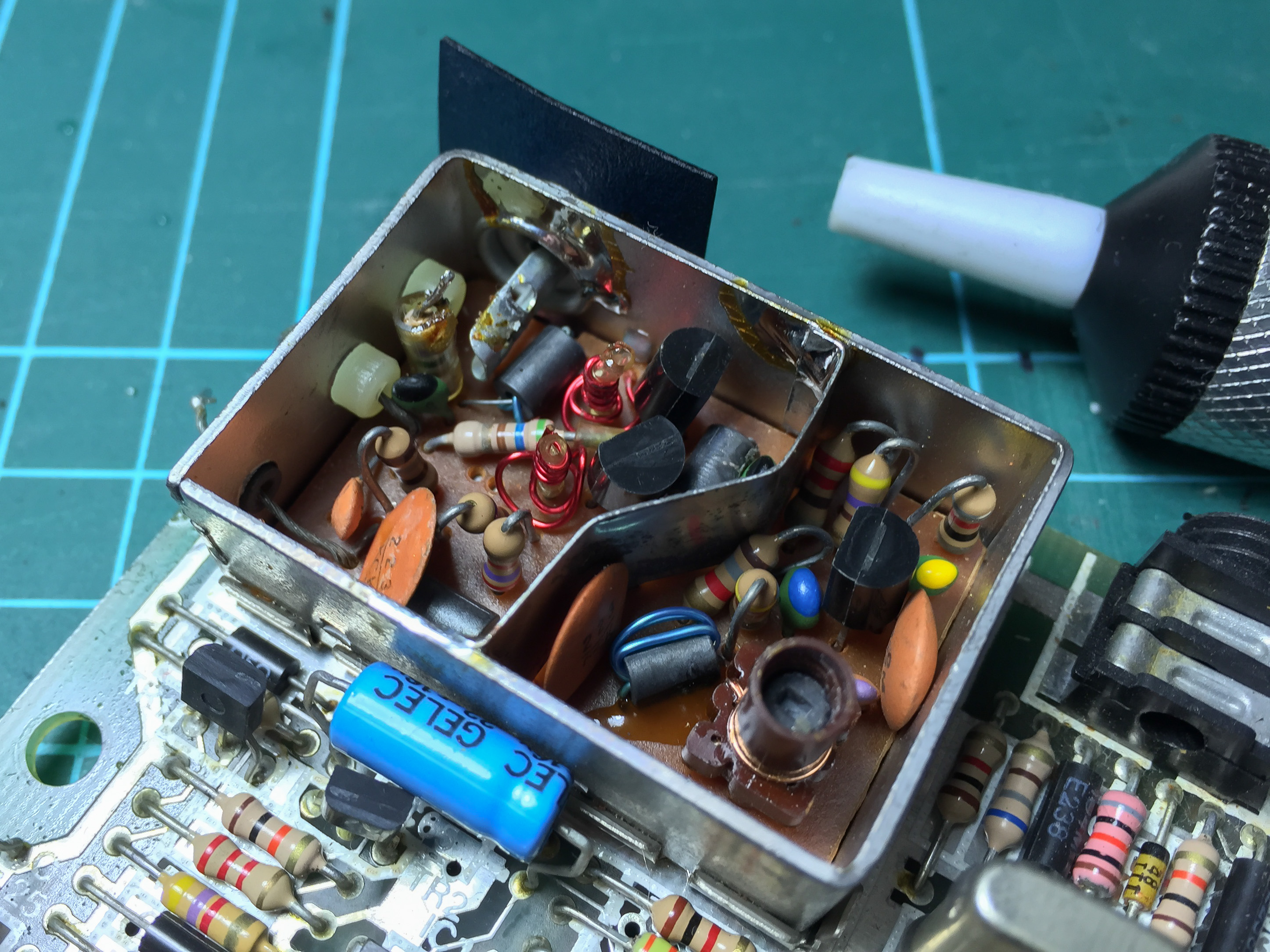
The image below shows the resistor once it has been detached and moved clear of the pole.
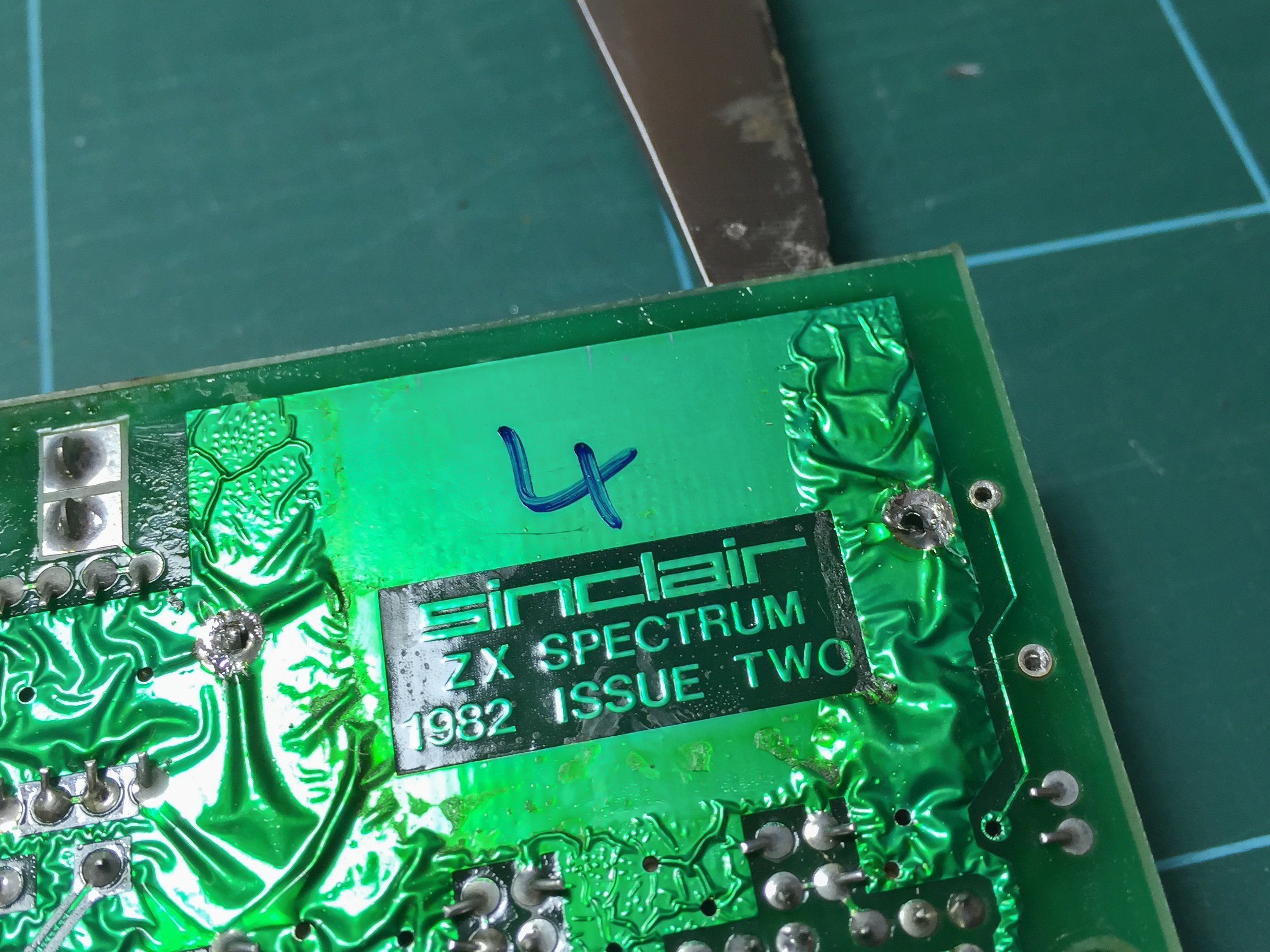
5: Desolder the modulator box anchor points⌗
Flip the main board over and desolder the modulator box’s anchor points (circled in the image below). A solder sucker or desoldering iron is very useful here.
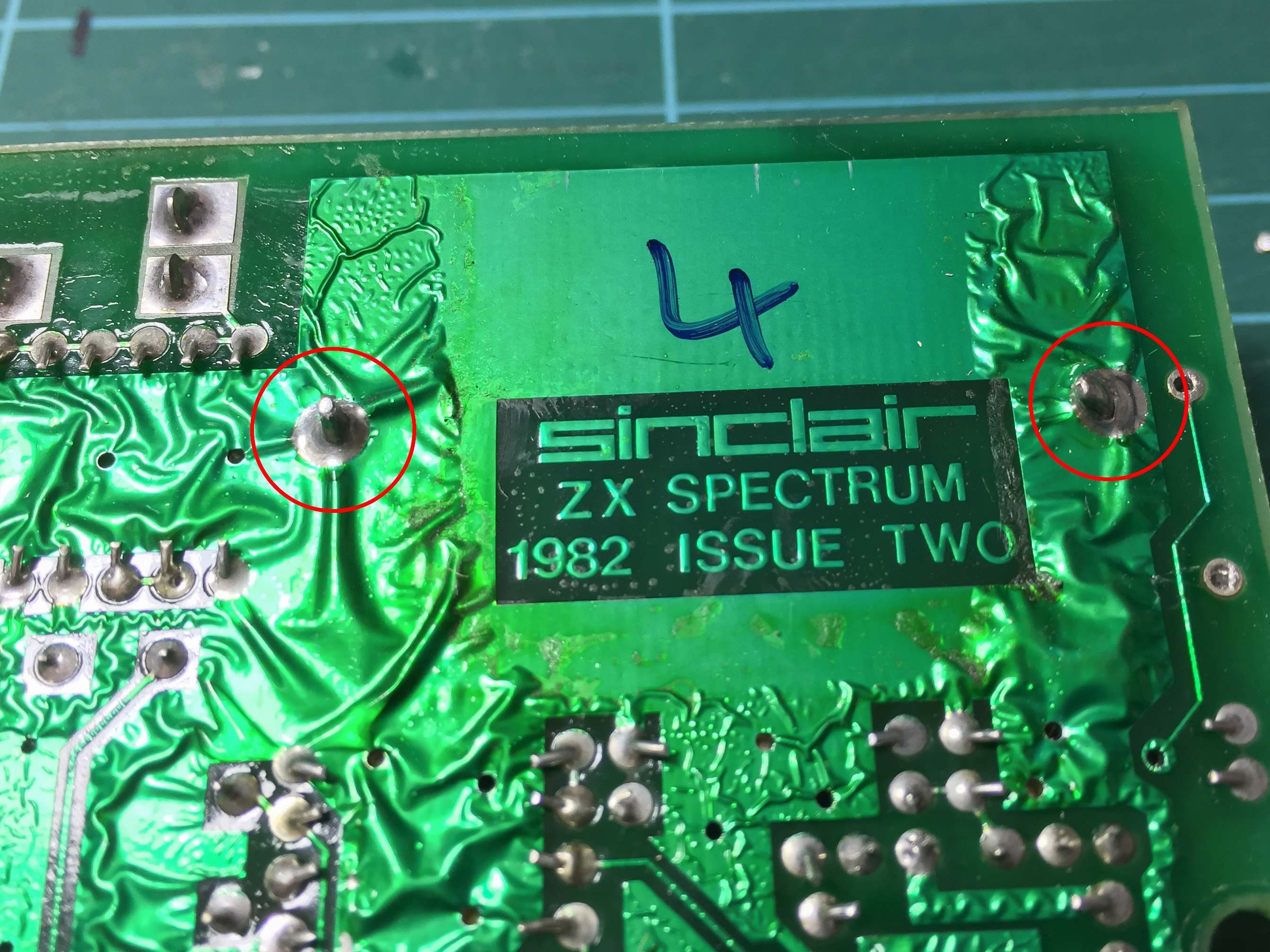
Once the solder is removed it should be possible to pull the modulator box (gently) away from the main board. Carefully prising it away (again, very gently) with a flat bladed screwdriver may be necessary. But only the minimum force should be required.
6: Remove the modulator box base⌗
This is the same procedure as the removing the lid: decrimp the edges of the base using a flat bladed screwdriver or needle nose pliers.
It make be necessary to remove additional solder from the modulator box legs to allow the base to be removed cleanly.
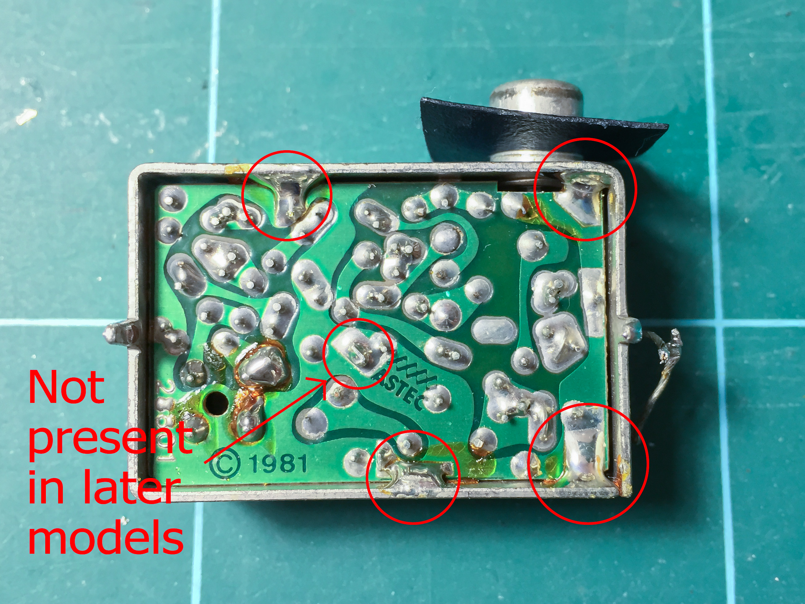
7: Remove the modulator circuit board⌗
With the resistor separated from the socket pole all that holds the modulator circuit board in place are its anchor points. Depending on the model of Spectrum there will be either four of these (round the edge, see image below) or five (as before but with an additional centre one). Once the solder is removed the circuit will pop out. As this modification is reversible you can keep the circuit board so it can be reinstalled at a later date (if for some reason you want to restore the RF output).
8: Attach the output capacitor⌗
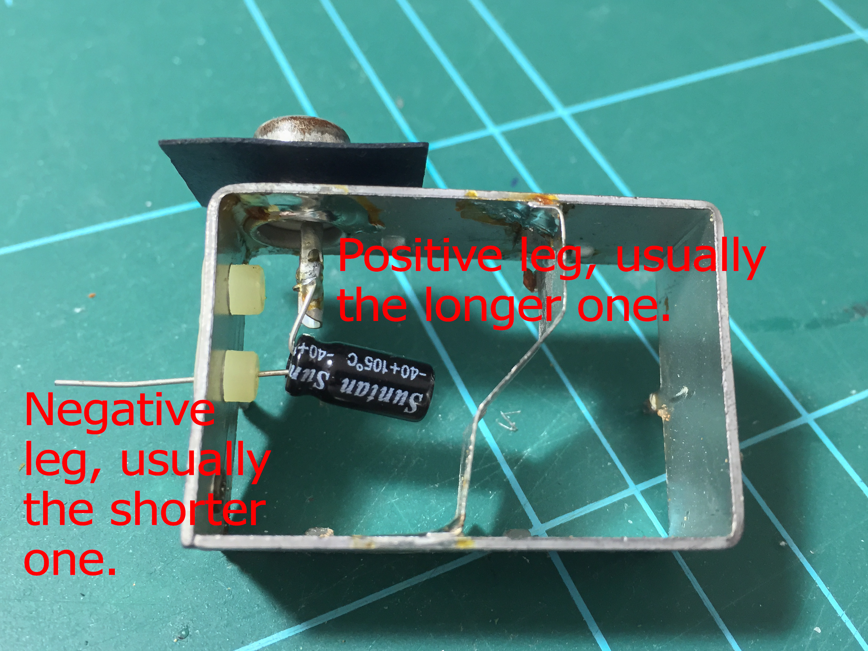
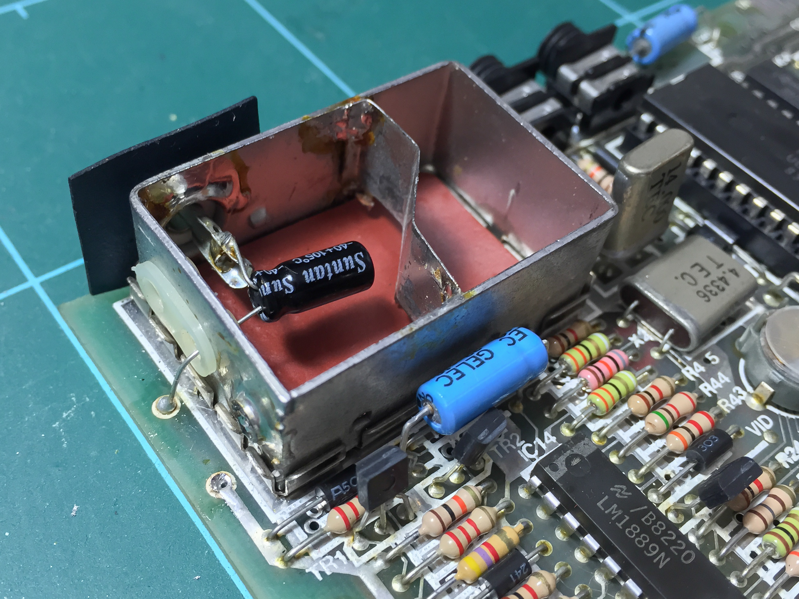
Solder a 100uF 10V capacitor to the socket pole. The positive leg should be attached to the pole while the negative leg should be threaded through the insulated hole in the side of the modulator box. For reference the positive leg is the longer one.
9: Reassemble the modulator box and attach the capacitor to the main board⌗
Now the modulator box can be reassembled: just push the base and lid in to place and gently fold the crimps back against the sides. Then the resealed modulator box can be put back on the main board and the anchors soldered in to place.
Bend the leg of the capacitor protruding from the modulator down to the composite output point on the main board (see image) and solder it in to place. Now is the time to connect the (formerly RF, now composite) socket to a monitor/TV and power up the Spectrum. Hopefully the “(c)1982 Sinclair Research Ltd” text should be seen all its composite glory.
Assuming everything is working (if it’s not, make sure that the capacitor is round the right way and attached to the correct output) the keyboard can be reattached (again, being careful with the ribbon cables) and the Spectrum closed up.
As previously mentioned this modification is entirely reversible. Just remove the capacitor, reattach the output resistor to the socket pole and then reconnect the two wires to the main board. However given the rarity of analogue TV tuners in modern televisions there isn’t any advantage to this other than originality of hardware.
Similarly a destructive modification can be made by drilling an extra hole in the case and attaching an RCA socket. The a wire from the composite output point on the motherboard can be attached to the centre pole of the new socket while the outer ring should be attached to a ground point (such as the modulator box casing). This allows for both RF and composite output from the same Speccy.