The Dragon 32 (aka the Welsh Tandy TRS-80 Color Computer clone) has many features that were advanced for its time. Unfortunately amongst these are two analogue joystick ports. Capable of six-bit resolution on each axis they are quite nice, except for playing games with. The vast majority of Dragon 32/TRS-80 games were ports from other systems and designed for digital controls. Luckily it’s possible to create an adapter that allows digital controls to be used with the Dragon 32. Very luckily in fact; as it’s basically impossible to find a working Dragon 32 analogue joystick these days.
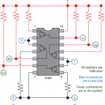
The adapter accepts a standard 9-pin Atari (or Kempston for old Spectrum owners) joystick plug and converts the digital signals in to the analogue input required by the Dragon 32. It does this by acting as two voltage splits, one for each axis. Taking the X (left-right) axis as an example. When neither direction is selected (the joystick is central) the voltage is split equally between ground and the Dragon’s X pin. This 50% voltage (actually 2.5v) is handled as centred by the games. When left is selected the voltage is shorted to ground and the Dragon’s X pin registers 0% (0v); this is handled as full left by the games. Finally when right is selected the connection with ground is broken and 100% (5v) goes to the Dragon’s X pin; which is handled as full right by games. The same applies to the vertical axis.
The achieve this in a compact form a 4066 IC is used. This contains the required four switches (two for each axis). A resistor goes before the positive input to the two switches and after the ground output. The Dragon’s pin is connected between the two switches. Additional resistors are required for the inputs to the switches. See the schematic for details.
The directions (and fire button) in an Atari joystick short to ground when activated. Thus the control voltage to the switches are cut when a certain direction is selected, resulting in the desired voltage split. The fire button works identically for both Atari and Dragon 32 standards and so is direct connection.
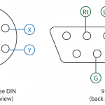
Any reasonably high resistance will do (I used 100K-Ohm) as long as all the resistors have an identical value. The Dragon 32 uses a 240 degree, 5 pin DIN plug which can be tricky to find these days. I found one being sold on eBay. The Atari socket is standard 9 pin D-Sub and can be found almost anywhere.
The same circuit can be used for the two button TRS-80 machines (using a Master System controller for example). The extra fire button pin on the Atari socket should be attached to the central pin that’s present on such plugs (240 degree, six pin DIN).


very nice, one correction I would like to make is that the dragon joystick ports use 240 degree 5 pin din
i meant in the picture for the diagram of the pinout, everything else is correctly saying 240 degree
Thanks spotting the typo! The diagram has been corrected.
I’ve searched high and low, and can’t find any Dragon 32 Joystick adapters for sale. I’m not good at making one myself. Could you tell me where I can purchase one? That would be kind. It seems there was one produced back then, but I guess they rarely comes up on Ebay 🙁
They are really hard to find these days. Occasionally one pops up on eBay, but the Dragon wasn’t exactly a popular computer so accessories are rare compared to the equivalent C64/Spectrum items. That’s why I ended up building my own adapter. I couldn’t find a prebuilt one but did find someone selling a severed Dragon joystick cable.
Do you produce your adapter for sale? I just bought a Dragon 32 on Ebay with 2 working Joysticks, but I don’t really like them LOL
So, the reason no one is making one for selling on, is that the market isn’t big enough? 🙁
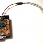
Thanks Vrai, I made my board using your design. Works perfectly. I upped a small video also.
https://www.youtube.com/channel/UCI5d7zJwG1QhZXo3VZG4BGA
https://www.youtube.com/watch?v=jNqp3WEqptA
With the 2 Player Connector the Retro Adapter switches to dual joystick mode. In this mode the computer sees two separate joysticks attached, one for each player. You can then select one joystick per player in emulators.
It is not easy to find out a 5 DIN 240 degree male socket so the easiest thing is to grab a 6 DIN and remove the center pin with solder heat or trim it.
Can you confirm that the pinout of the 5 DIN and 9 SUB connectors are respectively from the female connector on the Dragon32 and on the Joystick?
Hi,
I did this adapter, all is working except the fire button :-(. I have checked a good continuity on the Fire pin to the board. Do I need to GND the fire input also?
Thanks,
Rick
The joystick will connect the fire pin to ground via the fire button switch (completing the circuit when fire is pressed. This works the same for Dragon and Atari style joysticks, so you only need to pass through the signal from the DIN to the DB9.
You can check the fire button on the Dragon is working properly by just shorting the fire pin to ground on the computer. This will simulate holding the fire button down.
Pingback: Dragon 32 - 64k RAM upgrade and mods - retrohax.net